Virtual Synchronous Machine
The Virtual Synchronous Machine (VSM) is a control structure for a grid-forming converter, a type of DC/AC converters that set the voltage magnitude and angle at their point of connection.
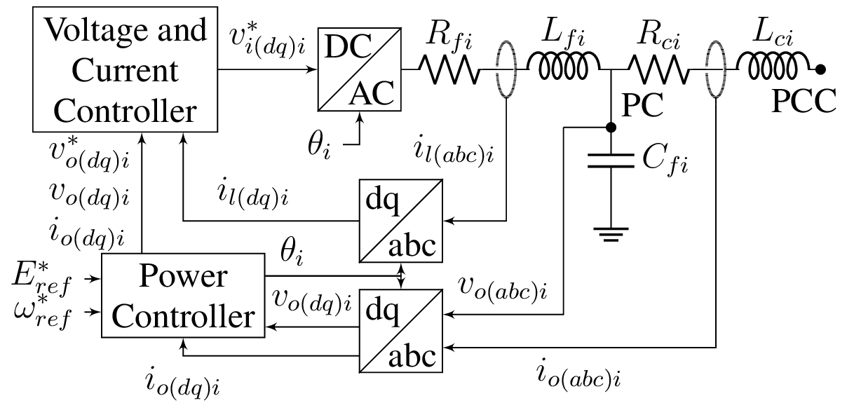
The abc/dq blocks represent the well-known Park's transform, a reference frame change which transfoms the 3 phase voltage signal to a rotating $dq0$ frame. Considering only balanced voltage, homopolar component can be discarded. This model considers a power invariant Park's transform, in which the power is: $$ P = v_{odi}i_{odi} + v_{oqi}i_{oqi} \hspace{2cm} Q = v_{oqi}i_{odi} - v_{odi}i_{oqi} $$
Level 0 control
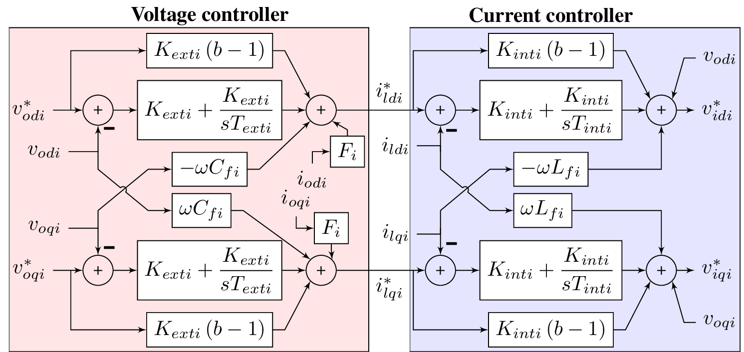
In general, the inner voltage and current controllers of an electronic converter are not considered part of the hierarchical microgrid control, and are included in a control layer level 0 control. This is the fastest control layer. Among other purposes, it is usually in charge of following the inner voltage and current references and limitating the output current of the converter when a fault occurs.Voltage and Current Controller
In this model, the user can choose the complexity of the voltage and current controllers between dynamic behavior, static behavior or static behavior for current controller including dynamic behavior for voltage controller.Dynamic voltage and current controllers
Static voltage and current controllers
If the voltage and current controllers dynamics are not relevant, they can be eliminated. Therefore, in the reduced system the converter is supposed to set the voltage reference at its output instantaneously: \begin{equation} v_{i d i}^{*}=v_{o d i} \hspace{2cm} v_{i q i}^{*}=v_{o q i} \end{equation}Static current controller and dynamic voltage controller
If the voltage controller dynamics are relevant, but the current controller dynamics are not relevant, the reduced system is supposed to set the current reference of the inner inductance instantaneously.Primary control
The primary control is the one in charge of stabilizing the voltage and frequency of the GFr after a disturbance.Power Controller
The power controller of a VSM mimics the behavior of a synchronous machine, with the swing equation and the governor equation. The power controller is in charge of stabilizing the frequency of the VSM after a disturbance: $$ \frac{d\omega}{dt} = T_m - T_e - 1/R_p \cdot(\omega-\omega_{ref}) - D \cdot \omega $$ where $T_m$ is the mechanical torque, $T_e$ is the electrical torque, $R_p$ is the power droop coefficient and $D$ is the damping coefficient. A droop controller is implemented to set the voltage reference of the VSM, which is a function of the reactive power injected by the converter: $$ v_{ref} = v_{ref0} - n_Q \cdot (Q - Q_{ref}) $$ where $v_{ref0}$ is the initial voltage reference, $n_Q$ is the droop coefficient for reactive power and $Q_{ref}$ is the reference reactive power.Virtual Impedance
The output virtual impedance, among other objectives, can guarantee the proper functionality of the droop even with resistive lines, by changing the output impedance seen by the converter. Since it is a virtual impedance, it does not involve a power loss. This model uses a virtual impedance approach based on the one in [2].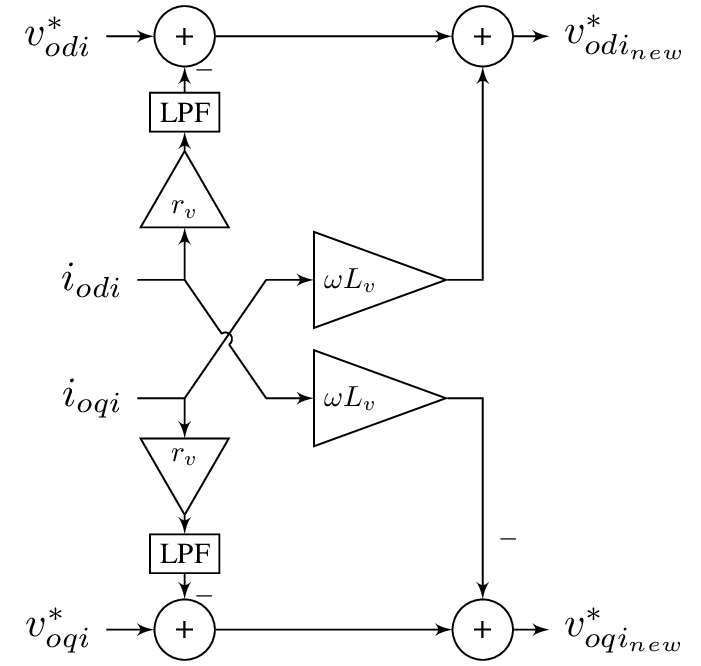
References
[1]
A. Bidram, V. Nasirian, A. Davoudi, and F. L. Lewis, Cooperative Synchronization in Distributed Microgrid Control. Cham, Switzerland: Springer International Publishing, 2017. doi: 10.1007/978-3-319-50808-5.
[2]
S. D’Arco, J. A. Suul, and O. B. Fosso, “A Virtual Synchronous Machine implementation for distributed control of power converters in SmartGrids,” Electric Power Systems Research, vol. 122, pp. 180–197, May 2015, doi: 10.1016/j.epsr.2015.01.001.